
Page 247 - Op Amps Design, Applications, and Troubleshooting
P. 247
Bandpass Filter 229
amp filter circuit can be used. For higher Qs, a cascaded filter should be used to
avoid potential oscillation problems.
5.4.1 Operation
To help us gain an intuitive understanding of the circuit's operation, let us draw
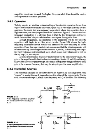
equivalent circuits for the filter shown in Figure 5.12 at very high and very low fre-
quencies. To obtain the low-frequency equivalent where the capacitors have a
high reactance, we simply open-circuit the capacitors. Figure 5.13 shows the low-
frequency equivalent; it is obvious from it that the low frequencies will never
reach the amplifier's input and therefore cannot pass through the filter.
At high frequencies, the reactance of the capacitors will be low and the
capacitors will begin to act like short circuits. Figure 5.14 shows the high-
frequency equivalent circuit, which was obtained by short-circuiting all of the
capacitors. From this equivalent circuit, we can see that the high frequencies will
be attenuated by the voltage divider action of RI and K 2- Additionally, the ampli-
fier has 0 resistance in the feedback loop, which causes our voltage gain to be 0 for
the op amp (i.e., no output).
At some intermediate frequency (determined by the component values), the
gain of the amplifier will offset the loss in the voltage divider (Ri and R 2) and the sig-
nals will be allowed to pass through. The circuit is frequently designed to have unity
gain at the resonant frequency, but may be set up to provide some amplification,
5.4.2 Numerical Analysis
The numerical analysis of the filter shown in Figure 5.12 can range from very
"messy" to straightforward, depending on the ratios of the components. That is,
each component except JR 4 affects both frequency and Q of the filter. The following
FIGURE 5.13
A low-frequency equivalent circuit for
the bandpass filter shown in Figure
5.12.
R, 1.4110
FIGURE 5.14
A high-frequency equivalent circuit for
the bandpass fitter shown in Figure
5.12.