
Page 252 - Op Amps Design, Applications, and Troubleshooting
P. 252
234 ACTIVE FILTERS
In the present case,/ H is estimated as
The required bandwidth for the op amp is computed in the same manner as
described in Chapter 2. It can be computed as
=
fuc A V/H
= 1 x 8.4 kHz
= 8AkHz
This is well within the capabilities of the standard 741 op amp.
Slow Rate. The minimum slew rate for the op amp can be computed with
Equation (5.7).
slew rate(min) = nf Ht> o(max)
= 3.14 x 8.4 kHz x 26 V
= 0.686 V/fis
This exceeds the capability of the standard 741, which has a 0.5-volts-per-
microsecond slew rate. We will use an MC1741SC for our design because it satis-
fies both the bandwidth and slew rate requirements of our design.
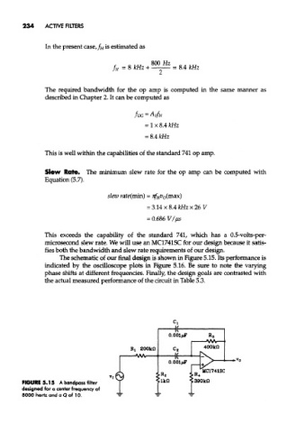
The schematic of our final design is shown in Figure 5.15. Its performance is
indicated by the oscilloscope plots in Figure 5.16. Be sure to note the varying
phase shifts at different frequencies. Finally, the design goals are contrasted with
the actual measured performance of the circuit in Table 5.3.
FIGURE 5.15 A bandpass filter
designed for a center frequency of
8000 hertz and a Q of 10.