
Page 255 - Op Amps Design, Applications, and Troubleshooting
P. 255
Band Reject Filter 237
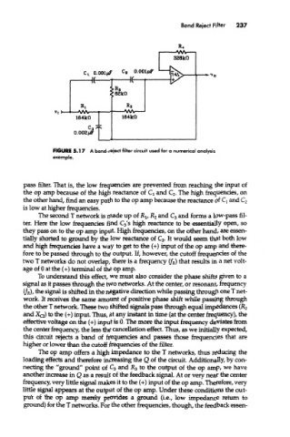
FIGURE 5.17 A band-reject filter circuit used for a numerical analysis
example.
pass filter. That is, the low frequencies are prevented from reaching the input of
the op amp because of the high reactance of Q and C 2. The high frequencies, on
the other hand, find an easy path to the op amp because the reactance of Q and C 2
is low at higher frequencies.
The second T network is made up of R v R 2 and C 3 and forms a low-pass fil-
ter. Here the low frequencies find C 3's high reactance to be essentially open, so
they pass on to the op amp input. High frequencies, on the other hand, are essen-
tially shorted to ground by the low reactance of C 3. It would seem that both low
and high frequencies have a way to get to the (+) input of the op amp and mere-
fore to be passed through to the output. If, however, the cutoff frequencies of the
two T networks do not overlap, there is a frequency (f R) that results in a net volt-
age of 0 at the (+) terminal of the op amp.
To understand this effect, we must also consider the phase shifts given to a
signal as it passes through the two networks. At the center, or resonant, frequency
(f R), the signal is shifted in the negative direction while passing through one T net-
work. It receives the same amount of positive phase shift while passing through
the other T network. These two shifted signals pass through equal impedances (R 2
and XQ) to the (+) input. Thus, at any instant in time (at the center frequency), the
effective voltage on the (+) input is 0. The more the input frequency deviates from
the center frequency, the less the cancellation effect. Thus, as we initially expected,
this circuit rejects a band of frequencies and passes those frequencies mat are
higher or lower than the cutoff frequencies of the filter.
The op amp offers a high impedance to the T networks, thus reducing the
loading effects and therefore increasing the Q of the circuit. Additionally, by con-
necting the "ground" point of C 3 and R 3 to the output of the op amp, we have
another increase in Q as a result of the feedback signal. At or very near the center
frequency, very little signal makes it to the (+) input of the op amp. Therefore, very
little signal appears at the output of the op amp. Under these conditions the out-
put of the op amp merely provides a ground (i.e., low impedance return to
ground) for the T networks. For the other frequencies, though, the feedback essen-