
Page 254 - Op Amps Design, Applications, and Troubleshooting
P. 254
236 ACTIVE FILTERS
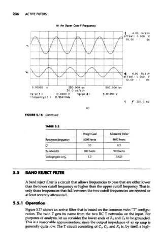
At the Upper Cutoff Frequency
FIGURE 5.16 Continued
TABLE 5.3
Design Goal Measured Value
Resonant frequency 8000 hertz 8080 hertz
Q 10 8.3
Bandwidth 800 hertz 973 hertz
Voltage gain ai/ R 1.0 0.825
5.5 BAND REJECT FILTER
A band reject filter is a circuit that allows frequencies to pass that are either lower
than the lower cutoff frequency or higher than the upper cutoff frequency. That is,
only those frequencies that fall between the two cutoff frequencies are rejected or
at least severely attenuated.
5.5.1 Operation
Figure 5.17 shows an active filter that is based on the common twin "T" configu-
ration. The twin T gets its name from the two RC T networks on the input. For
purposes of analysis, let us consider the lower ends of R 3 and C 3 to be grounded.
This is a reasonable approximation, since the output impedance of an op amp is
generally quite low. The T circuit consisting of Q, C 2, and R 3 is, by itself, a high-