
Page 235 - Op Amps Design, Applications, and Troubleshooting
P. 235
Low-Pass Filter 217
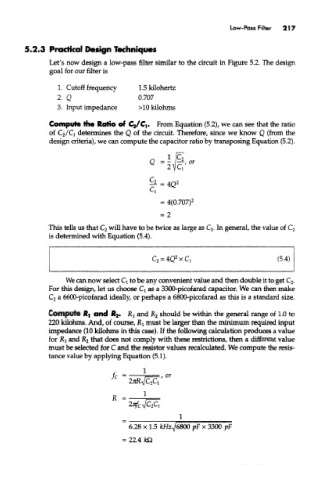
5.2*3 Practical Design Techniques
Let's now design a low-pass filter similar to the circuit in Figure 5,2. The design
goal for our filter is
1. Cutoff frequency l.Skilohertz
2. Q 0.707
3. Input impedance >10kilohms
Compute the Ratio of Cj/Ci. From Equation (5.2), we can see that the ratio
of C 2/C] determines the Q of the circuit. Therefore, since we know Q (from the
design criteria), we can compute the capacitor ratio by transposing Equation (5.2).
This tells us mat C 2 will have to be twice as large as Q. In general, the value of C 2
is determined with Equation (5.4).
We can now select Q to be any convenient value and then double it to get C 2.
For this design, let us choose Q as a 3300-picofarad capacitor. We can men make
C 2 a 6600-pkofarad ideally, or perhaps a 6800-pieofarad as this is a standard size.
Compute ft, and R& RI and K 2 should be within the general range of 1.0 to
220 kilohms. And, of course, R l must be larger than the minimum required input
impedance (10 kilohms in this case). If the following calculation produces a value
for RI and R 2 that does not comply with these restrictions, then a different value
must be selected for C and the resistor values recalculated. We compute the resis-
tance value by applying Equation (5.1).