
Page 234 - Op Amps Design, Applications, and Troubleshooting
P. 234
216 ACTIVE FILTERS
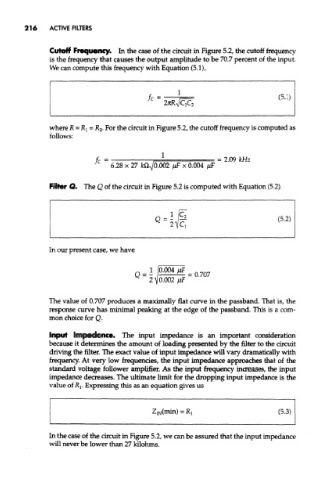
Cutoff Frequency. In the case of the circuit in Figure 5.2, the cutoff frequency
is the frequency that causes the output amplitude to be 70.7 percent of the input.
We can compute this frequency with Equation (5.1),
where R = RI = R 2- For the circuit in Figure 5.2, the cutoff frequency is computed as
follows:
Filler Q. The Q of the circuit in Figure 5.2 is computed with Equation (5.2),
In our present case, we have
The value of 0.707 produces a maximally flat curve in the passband. That is, the
response curve has minimal peaking at the edge of the passband. This is a com-
mon choice for Q.
Input Impedance. The input impedance is an important consideration
because it determines the amount of loading presented by the filter to the circuit
driving the filter. The exact value of input impedance will vary dramatically with
frequency. At very low frequencies, the input impedance approaches that of the
standard voltage follower amplifier. As the input frequency increases, the input
impedance decreases. The ultimate limit for the dropping input impedance is the
value of RI. Expressing this as an equation gives us
In the case of the circuit in Figure 5.2, we can be assured that the input impedance
will never be lower than 27 kilohms.