
Page 267 - Op Amps Design, Applications, and Troubleshooting
P. 267
Voltage Regulation Fundamentals 249
There are many types of voltage regulator circuits, but the purpose remains
the same—to maintain a constant output voltage even though both the input volt-
age and the load current may be changing. The regulated output voltage is always
less than the unregulated input voltage.
We will examine three basic classes of voltage regulator circuits:
1. Series
2. Shunt
3. Switching
6.1.1 Series Regulation
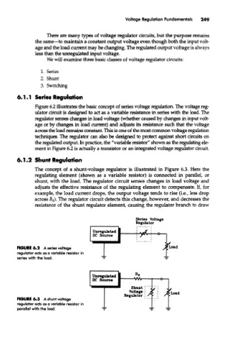
Figure 6.2 illustrates the basic concept of series voltage regulation. The voltage reg-
ulator circuit is designed to act as a variable resistance in series with the load. The
regulator senses changes in load voltage (whether caused by changes in input volt-
age or by changes in load current) and adjusts its resistance such that the voltage
across the load remains constant. This is one of the most common voltage regulation
techniques. The regulator can also be designed to protect against short circuits on
the regulated output. In practice, the "variable resistor" shown as the regulating ele-
ment in Figure 6.2 is actually a transistor or an integrated voltage regulator circuit.
6.1.2 Shunt Regulation
The concept of a shunt-voltage regulator is illustrated in Figure 6.3. Here the
regulating element (shown as a variable resistor) is connected in parallel, or
shunt, with the load. The regulator circuit senses changes in load voltage and
adjusts the effective resistance of the regulating element to compensate. If, for
example, the load current drops, the output voltage tends to rise (i.e., less drop
across R s). The regulator circuit detects this change, however, and decreases the
resistance of the shunt regulator element, causing the regulator branch to draw
FIGURE 6.2 A series voltage
regulator acts as a variable resistor in
series with the load.
FIGURE 6.3 A shunt voltage
regulator acts as a variable resistor in
parallel with the load.