
Page 268 - Op Amps Design, Applications, and Troubleshooting
P. 268
250 POWER SUPPLY CIRCUITS
more current and the current through R$ to remain constant, and preventing the
output voltage from rising.
The shunt regulator is generally used for low-current applications because it
consumes a significant amount of power. A simple zener diode is an example of a
shunt regulator. By adding an op amp, however, the degree of regulation can be
improved.
6.1.3 Switching Regulation
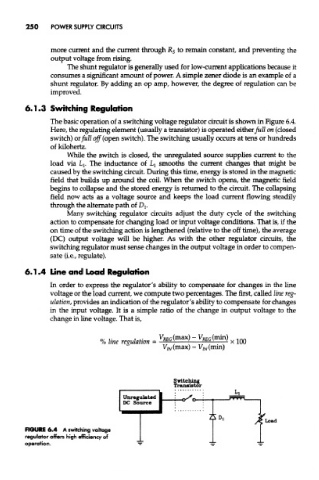
The basic operation of a switching voltage regulator circuit is shown in Figure 6.4.
Here, the regulating element (usually a transistor) is operated either full on (closed
switch) or full off (open switch). The switching usually occurs at tens or hundreds
of kilohertz.
While the switch is closed, the unregulated source supplies current to the
load via Lj. The inductance of LI smooths the current changes that might be
caused by the switching circuit. During this time, energy is stored in the magnetic
field that builds up around the coil. When the switch opens, the magnetic field
begins to collapse and the stored energy is returned to the circuit. The collapsing
field now acts as a voltage source and keeps the load current flowing steadily
through the alternate path of Dj.
Many switching regulator circuits adjust the duty cycle of the switching
action to compensate for changing load or input voltage conditions. That is, if the
on time of the switching action is lengthened (relative to the off time), the average
(DC) output voltage will be higher. As with the other regulator circuits, the
switching regulator must sense changes in the output voltage in order to compen-
sate (i.e., regulate).
6.1,4 Line and Load Regulation
In order to express the regulator's ability to compensate for changes in the line
voltage or the load current, we compute two percentages. The first, called line reg-
ulation, provides an indication of the regulator's ability to compensate for changes
in the input voltage. It is a simple ratio of the change in output voltage to the
change in line voltage. That is,
FIGURE 6.4 A switching voltage
regulator offers high efficiency of
operation.