
Page 283 - Op Amps Design, Applications, and Troubleshooting
P. 283
Shunt Voltage Regulation 265
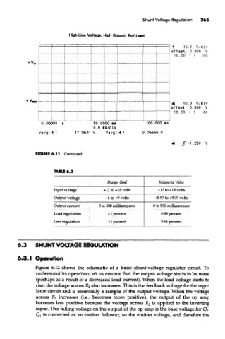
High Line Voltage, High Output, Full Load
FIGURE 6.11 Continued
TABLE 6.2
Design Goal Measured Value
Input voltage +12 to +18 volts +12 to +18 volts
Output voltage +6 to +9 volts +5.97 to +9.07 volts
Output current 0 to 500 milliamperes 0 to 500 milliamperes
Load regulation <1 percent 0.99 percent
Line regulation <1 percent 0.56 percent
6.3 SHUNT VOLTAGE REGULATION
6*3.1 Operation
Figure 6.12 shows the schematic of a basic shunt-voltage regulator circuit. To
understand its operation, let us assume that the output voltage starts to increase
(perhaps as a result of a decreased load current). When the load voltage starts to
rise, the voltage across R 2 also increases. This is the feedback voltage for the regu-
lator circuit and is essentially a sample of the output voltage. When the voltage
across R 2 increases (i.e., becomes more positive), the output of the op amp
becomes less positive because the voltage across R 2 is applied to the inverting
input. This falling voltage on the output of the op amp is the base voltage for Qj.
Q l is connected as an emitter follower, so the emitter voltage, and therefore the