
Page 281 - Op Amps Design, Applications, and Troubleshooting
P. 281
Series Voltage Regulators 263
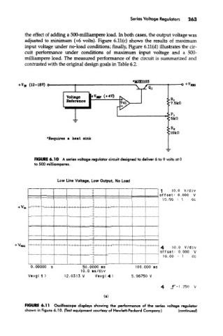
the effect of adding a 500-milliampere load. In both cases, the output voltage was
adjusted to minimum (+6 volts). Figure 6.11(c) shows the results of maximum
input voltage under no-load conditions; finally, Figure 6.11(d) illustrates the cir-
cuit performance under conditions of maximum input voltage and a 500-
milliampere load. The measured performance of the circuit is summarized and
contrasted with the original design goals in Table 6.2.
•MJE1103
FIGURE 6*11 Oscilloscope displays showing the performance of the series voltage regulator
shown in Figure 6.10. (Test equipment courtesy of Hewlett-Packard Company.) (continued)