
Page 285 - Op Amps Design, Applications, and Troubleshooting
P. 285
Shunt Voltage Regulation 267
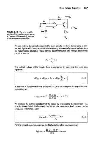
FIGURE 6.13 The error amplifier
portion of the regulator circuit shown
in Figure 6.12 is essentially a simple
noniriverting voltage amplifier.
We can redraw the circuit somewhat to more clearly see how the op amp is con-
nected. Figure 6.13 clearly shows that the op amp is essentially connected as a sim-
ple noninvertiong amplifier with a current-boost transistor. The voltage gain of this
circuit is simply
The output voltage of the circuit, then, is computed by applying the basic gain
equation.
In the case of the circuit shown in Figure 6.12, we can compute the regulated out-
put voltage as
We estimate the current capability of the circuit by considering the case when +V m
is at its lowest level. Under these conditions, the maximum load current can be
estimated with Ohm's Law.
For the present case, we compute the highest allowable load current as