
Page 284 - Op Amps Design, Applications, and Troubleshooting
P. 284
266 POWER SUPPLY CIRCUITS
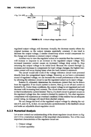
FIGURE 6.12 A shunt voltage regulator circuit.
regulated output voltage, will decrease. Actually, the decrease merely offsets the
original increase, so the output remains essentially constant. If one tried to
decrease the output voltage, a similar closed-loop action would compensate for
the change and maintain a constant output voltage.
Another way to view the regulator action is to consider that the current in Q}
will increase in response to an increase in the regulated output voltage. This
increased transistor current causes an increased voltage drop across R 3, thus
returning the output voltage to its initial level. Because the current through Q l
increases and decreases to compensate for load voltage changes, the highest tran-
sistor current will occur during times when the load current is minimum.
The circuit would still work if the voltage reference circuit were powered
directly from the unregulated input voltage. However, as we have a convenient
source of regulated voltage, we can increase the overall performance of the circuit
by allowing the reference circuit to use the regulated output as its input voltage.
Resistor R 3 ultimately determines the maximum current that can be drawn
from the regulator. If too much current is drawn, then Qi is cut off and current is
limited by JR 3. Under these conditions, the output voltage is not regulated and will
decrease with increasing load currents. The circuit does have a distinct advantage
in that it is inherently current limited. That is, if a short-circuit to ground occurs on
the regulated voltage line, the current is limited by resistor R 3. No other regulator
components will experience an overload condition. If this resistor has an adequate
power rating, no damage will result from shorted outputs.
We can change the level of the regulated output voltage by altering the val-
ues of RI and/or R 2. In fact, we can include a potentiometer in the feedback circuit
and make an adjustable shunt-regulator circuit.
6.3.2 Numerical Analysis
Let us now extend our understanding of the shunt regulator circuit shown in Fig-
ure 6.12 to a numerical analysis of the important characteristics. Two of the most
important characteristics of the regulator circuit are
1. Output voltage
2. Current capability