
Page 353 - Op Amps Design, Applications, and Troubleshooting
P. 353
Differentiator 331
which shows that the opposition to current flow decreases as the frequency (rate
of change of voltage) increases. In the case of the circuit shown in Figure 7,24, we
can expect capacitor Q to have greater currents for input voltages that change lev-
els more quickly. Any current that flows through the capacitor must also flow
through RI because of the series connection. Since no significant current flows in
or out of the (-) input, we can conclude that the current through R 2 will also be the
same as the input current and will be proportional to the rate of change of input
voltage. The left end of R 2 is connected to a virtual ground point; therefore, the
voltage across it is the output voltage of the op amp and is determined by the rate
of change of input voltage.
The differentiator circuit is inherently unstable and prone to oscillation
because the input impedance decreases with increasing frequency. Recall that the
gain for an inverting op amp is determined by the ratio of the impedance in the
feedback path to the input impedance. Since the input impedance decreases with
frequency, it will cause the gain to increase at high frequencies. Even though the
actual input signal frequency may be relatively low, there are always high-
frequency noise signals present. If the gain were allowed to increase excessively at
high frequencies, these noise signals would interfere with the desired output and
could cause oscillation in the circuit. To prevent this gain, we include capacitor C 2
in the feedback path. This capacitor tends to bypass resistor R 2 at noise frequen-
cies, thus reducing the circuit gain and improving the circuit stability. Addition-
ally, resistor RI works to increase the stability by ensuring that the input
impedance has a practical minimum limit regardless of the frequency.
Resistor R 3 reduces the effects of the op amp bias current. As with previous
circuits, we make R 3 equal to R 2 so that the DC resistance in both op amp terminals
is the same. Capacitor C 3 simply bypasses R 3 at high frequencies, which further
minimizes the circuit's response to noise frequencies.
7.7.2 Numerical Analysis
Since the output voltage of a differentiator circuit is determined by the rate of
change of input voltage, we want to know the maximum rate of change of input
voltage that can be applied to the circuit without driving the circuit into satura-
tion. We can estimate this rate by applying Equation (7.17).
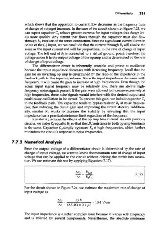
For the circuit shown in Figure 7.24, we estimate the maximum rate of change of
input voltage as
The input impedance is a rather complex issue because it varies with frequency
and is affected by several components. Nevertheless, the absolute rrdrdmum