
Page 348 - Op Amps Design, Applications, and Troubleshooting
P. 348
326 SIGNAL PROCESSING CIRCUITS
7.6.3 Practical Design Techniques
We will now design an op amp integrator that will perform according to the fol-
lowing design goals:
1. Input frequency 300 hertz to 20 kilohertz
2. Input impedance >1000 ohms
3. Input voltage 2 to 6.5 volts peak
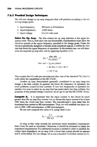
Select the Op Amp. The first criteria for op amp selection is the upper fre-
quency limit. That is, both slew rate and bandwidth considerations must allow the
circuit to operate at the upper frequency specified in the design goals. Unless the
circuit is specifically designed to handle small-amplitude signals, it will be the slew
rate that limits the upper frequency of operation. In the present case, we will deter-
mine the required op amp slew rate by applying Equation (2.11).
This exceeds the 0.5-volts-per-microsecond slew rate of the standard 741, but it is
well within the capabilities of the MC1741SC.
Another op amp characteristic generally considered in op amp integrator
design is the bias current. In general, the lower the frequency of operation, the
more problems caused by bias currents. If very low frequencies of operation are
needed, it is wise to select an op amp that has particularly low bias currents. For
purposes of the present design, however, let us opt to use the MC1741SC device,
Compute H|. It is important that the input current to the circuit be much
greater than the op amp bias current. Let us choose the input current to be at least
1000 times the worst-case bias current. The manufacturer's data sheet lists the
maximum bias current as 800 nanoamperes. Thus, we will establish our input cur-
rent at 1000 x 800 nanoamperes, or 800 microamperes.
We can now compute the value of RI using Ohm's Law.
As long as this value exceeds the minimum input impedance requirement,
then it may be used as calculated. Otherwise, it should be increased to satisfy the
impedance requirements. If a substantial increase is needed in order to establish the
correct input impedance, an op amp with a lower bias current should be selected
and R l recalculated. For our design, let us use a standard 2.4-kilohm resistor for R^