
Page 343 - Op Amps Design, Applications, and Troubleshooting
P. 343
Peak Detectors 321
Let us select a standard value of 120 kilohms for R 5.
Compute RI, Ha/ Ha/ and ft*. For our purposes, the exact values of these four
resistors are noncritical and any value in the range of 2 to 100 kilohms will suffice.
an tftat
It is important, however, that RI = K 2 d ^3 = &*• Let us arbitrarily choose all
four resistors to be 10 kilohms.
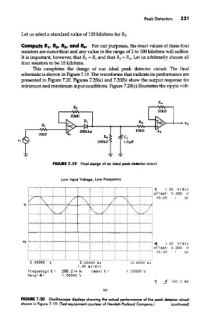
This completes the design of our ideal peak detector circuit. The final
schematic is shown in Figure 7.19. The waveforms mat indicate its performance are
presented in Figure 7.20. Figures 7.20(a) and 7.20(b) show the output response for
minimum and maximum input conditions. Figure 7.20(c) illustrates the ripple volt-
FIGURE 7.19 Final design of an ideal peak detector circuit.
Low Input Voltage, Low Frequency
FIGURE 7.20 Oscilloscope displays showing the actual performance of the peak detector circuit
shown in Figure 7.19. {Test equipment courtesy of Hewlett-Packard Company.) (continued)