
Page 338 - Op Amps Design, Applications, and Troubleshooting
P. 338
316 SIGNAL PROCESSING CIRCUITS
TABLE 7.3
Design Goals Measured Values
Minimum input impedance 1.1 kilohms 1.2 kilohms
Input voltage range 500 millivolts-2 volts (peak) 500 millivolts-2 volts (peak)
Reference levels -1 volt-2 volts (peak) -0.76 volts-2 volts (peak)
Minimum input frequency 20 hertz 20 hertz
7.5 PEAK DETECTORS
It is often necessary to develop a DC voltage that is equal to the peak amplitude of
an AC signal. This technique is used for many applications, including test equip-
ment, ultrasonic alarm systems, and music synthesizers. As with the other circuits
presented earlier in this chapter, the peak detector simulates an ideal diode by
including it in the feedback loop of an op amp.
7.5.1 Operation
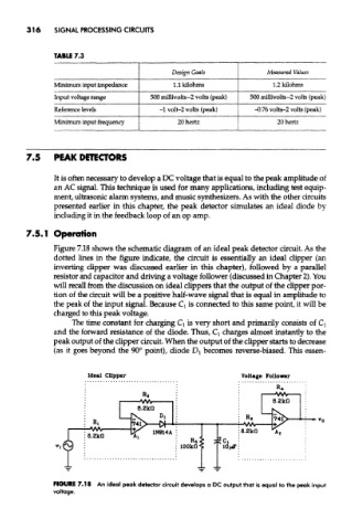
Figure 7.18 shows the schematic diagram of an ideal peak detector circuit. As the
dotted lines in the figure indicate, the circuit is essentially an ideal clipper (an
inverting clipper was discussed earlier in this chapter), followed by a parallel
resistor and capacitor and driving a voltage follower (discussed in Chapter 2). You
will recall from the discussion on ideal clippers that the output of the clipper por-
tion of the circuit will be a positive half-wave signal that is equal in amplitude to
the peak of the input signal. Because Q is connected to this same point, it will be
charged to this peak voltage.
The time constant for charging Q is very short and primarily consists of Q
and the forward resistance of the diode. Thus, Q charges almost instantly to the
peak output of the clipper circuit. When the output of the clipper starts to decrease
(as it goes beyond the 90° point), diode D x becomes reverse-biased. This essen-
F1GURE7.18 An ideal peak detector circuit develops a DC output that is equal to the peak input
voltage.