
Page 335 - Op Amps Design, Applications, and Troubleshooting
P. 335
Ideal Clamper 313
Low Frequency
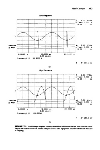
FIGURE 7.15 Oscilloscope displays showing the effects of internal delays and slew rate limit-
ing on the operation of the biased clamper circuit. (Test equipment courtesy of Hewlett-Packard
Company.)