
Page 345 - Op Amps Design, Applications, and Troubleshooting
P. 345
Integrator 323
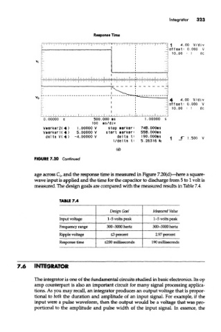
Response Time
FIGURE 7.20 Continued
age across Q, and the response time is measured in Figure 7.20(d)—here a square-
wave input is applied and the time for the capacitor to discharge from 5 to 1 volt is
measured. The design goals are compared with the measured results in Table 7.4.
TABLE 7.4
Design Goal Measured Value
Input voltage 1-5 volts peak 1-5 volts peak
Frequency range 300-3000 hertz 300-3000 hertz
Ripple voltage £3 percent 2.97 percent
Response time <200 milliseconds 190 milliseconds
7.6 INTEGRATOR
The integrator is one of the fundamental circuits studied in basic electronics. Its op
amp counterpart is also an important circuit for many signal processing applica-
tions. As you may recall, an integrator produces an output voltage that is propor-
tional to both the duration and amplitude of an input signal. For example, if the
input were a pulse waveform, then the output would be a voltage that was pro-
portional to the amplitude and pulse width of the input signal. In essence, the