
Page 349 - Op Amps Design, Applications, and Troubleshooting
P. 349
Integrator 327
Compute Ci. The basic electronics equations for charge (Q = CV and Q = It) can
be set equal to each other and manipulated to give us our equation, Equation
(7.16), for Q.
where f L is the lowest input frequency and z'j is the maximum input current. The
maximum input current is computed with Ohm's Law as
For our current design, we compute Q as
We will use a standard 0.33-microfarad capacitor for Q. A low-leakage type of
capacitor should be chosen.
Compute £2. Resistor R 2 is chosen to have a resistance of at least 10 times the
capacitive reactance of Q at the lowest input frequency. We simply apply the basic
capacitive reactance equation to compute R 2.
Compute £3. Resistor R 3 is computed as the parallel combination of RI and R 2.
That is,
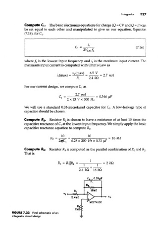
FIGURE 7.22 Final schematic of an
integrator circuit design.