
Page 352 - Op Amps Design, Applications, and Troubleshooting
P. 352
330 SIGNAL PROCESSING CIRCUITS
The completed integrator design is shown in Figure 7.22, and the circuit wave-
forms are presented in Figure 7.23. Figure 7.23(a) shows the response of the cir-
cuit at 300 hertz; notice the linearity of the ramp waveform. Figures 7.23{b) and
7.23(c) show the circuit response to 20-kilohertz signals. The integrator action
has essentially eliminated the observable waveform, but comparison of Figures
7.23(a) to 7.23(c) will clearly show the circuit's response to changes in duty cycle.
Figure 7.23{d) illustrates the circuit's response to a 6.5-volt peak input signal.
7.7 DIFFERENTIATOR
The differentiator is another fundamental electronic circuit and is the inverse of
the integrator circuit. In terms of mathematics, it produces an output signal that is
the first derivative of the input signal. In more intuitive terms, the instantaneous
output voltage is proportional to the instantaneous rate of change of input volt-
age. If, for example, we apply a linear ramp voltage to the input of a differentiator,
we will expect the output to be a IX! level since the rate of change of input voltage
is a constant value. Similarly, if we apply a sine wave to the differentiator, the out-
put will also be sinusoidal in shape but will be shifted in phase by approximately
90 degrees since the maximum rate of change of a sine wave occurs as it passes
through the 0° and 180° points.
7.7.1 Operation
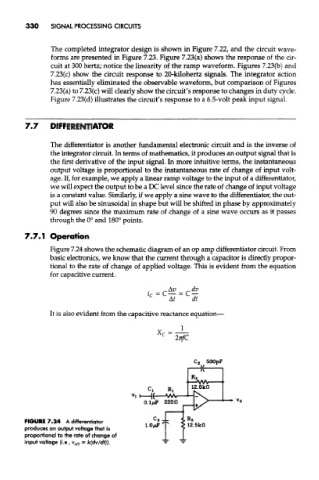
Figure 7.24 shows the schematic diagram of an op amp differentiator circuit. From
basic electronics, we know that the current through a capacitor is directly propor-
tional to the rate of change of applied voltage. This is evident from the equation
for capacitive current.
It is also evident from the capacitive reactance equation-
FIGURE7.24 A differentiator
produces an output voltage that is
proportional to the rate of change of
input voltage (i.e., v oW = kfdv/dfj).