
Page 360 - Op Amps Design, Applications, and Troubleshooting
P. 360
338 D!GITAL-TO-ANALOG AND ANALOG-TO-DIGITAL CONVERSION
understanding of the operation of these fundamental circuits is important because
they convey essential underlying principles. The actual implementation of the
converter circuits, however, is another matter. Except for unique or very demand-
ing applications (neither of which is targeted by this text), most A/D and D/A
converter applications are resolved by an integrated circuit version of the A/D or
D/A converter. The price and performance of these circuits makes them very dif-
ficult to beat by designing your own.
8.1 D/A AND A/D CONVERSION FUNDAMENTALS
The concepts and terminology presented in this chapter are important to the
reader whether designing a custom converter circuit or selecting an integrated
version. In either case, the technician or engineer must be able to effectively eval-
uate the application and contrast it with the specifications of the converter circuit.
8,1,1 Analog-to-Digital Converters
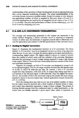
Figure 8.1 illustrates the fundamental function of A/D conversion. The block
labeled "A/D Converter" may be an integrated circuit or an array of op amps and
other devices. In any case, it accepts the analog signal as its input and produces a
corresponding digital output. The digital output is shown to consist of several
lines, the number of which varies with the resolution of the converter. Resolution
describes the percentage of input voltage change required to cause a step change
in the output. Table 8.1 shows the basic relationship between number of bits (lines)
and equivalent resolution.
Suppose, for example, an 8-bit A/D converter was designed to accept 0-volt
to 10-volt input signals. The 10-volt range would be divided into 256 discrete steps
of 10/256, or about 39 millivolts per step. By contrast, a 4-bit A/D converter
would have less resolution, with each of the 16 output steps being equivalent to
6.25 percent of the full-scale input, or 625 millivolts. Thus, the higher the resolu-
tion (i.e., the number of bits in the converted output), the smaller the input change
required to move to the next output step. Typical applications require resolutions
of 8,12, or 20 bits.
Since the analog input may take on any one of an infinite number of values
but the output must be resolved into a fixed number of discrete levels or steps,
each output step inherently represents a range of input voltages. The process of
forming discrete groups from the continuous input is called quantization, so the
output does not exactly represent a given input value; rather, it represents an
FIGURE 8.1 Analog-to-digital
conversion makes an analog signal
compatible with a digital system.