
Page 363 - Op Amps Design, Applications, and Troubleshooting
P. 363
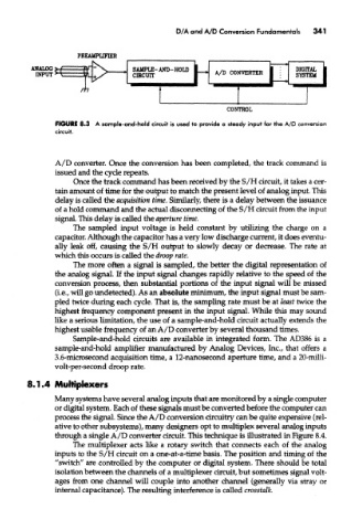
FIGURE 8.3 A sample-and-hold circuit is used to provide a steady input for the A/D conversion
               circuit.


               A/D converter. Once the conversion has been completed, the track command is
               issued and the cycle repeats.
                    Once the track command has been received by the S/H circuit, it takes a cer-
               tain amount of time for the output to match the present level of analog input This
               delay is called the acquisition time. Similarly, there is a delay between the issuance
               of a hold command and the actual disconnecting of the S/H circuit from the input
               signal. This delay is called the aperture time.
                    The sampled input voltage is held constant by utilizing the charge on a
               capacitor. Although the capacitor has a very low discharge current, it does eventu-
               ally leak off, causing the S/H output to slowly decay or decrease. The rate at
               which mis occurs is called the droop rate.
                    The more often a signal is sampled, the better the digital representation of
               the analog signal. If the input signal changes rapidly relative to the speed of the
               conversion process, then substantial portions of the input signal will be missed
               (i.e., will go undetected). As an absolute minimum, the input signal must be sam-
               pled twice during each cycle. That is, the sampling rate must be at least twice the
               highest frequency component present in the input signal. While this may sound
               like a serious limitation, the use of a sample-and-hold circuit actually extends the
               highest usable frequency of an A/D converter by several thousand times.
                    Sample-and-hold circuits are available in integrated form. The AD386 is a
               sample-and-hold amplifier manufactured by Analog Devices, Inc., that offers a
               3.6-microsecond acquisition time, a 12-nanosecond aperture time, and a 20-milli-
               volt-per-second droop rate.

        8.1.4 Multiplexers
               Many systems have several analog inputs that are monitored by a single computer
               or digital system. Each of these signals must be converted before the computer can
               process the signal. Since the A/D conversion circuitry can be quite expensive (rel-
               ative to other subsystems), many designers opt to multiplex several analog inputs
               through a single A/D converter circuit. This technique is illustrated in Figure 8.4.
                    The multiplexer acts like a rotary switch that connects each of the analog
               inputs to the S/H circuit on a one-at-a-time basis. The position and timing of the
               "switch" are controlled by the computer or digital system. There should be total
               isolation between the channels of a multiplexer circuit, but sometimes signal volt-
               ages from one channel will couple into another channel (generally via stray or
               internal capacitance). The resulting interference is called crosstalk.