
Page 361 - Op Amps Design, Applications, and Troubleshooting
P. 361
D/A and A/D Conversion Fundamentals 339
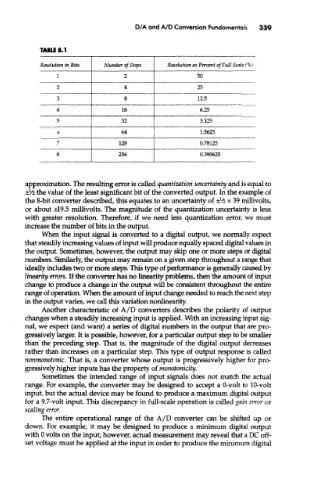
TABLE 8.1
Resolution in Bits Number of Steps Resolution as Percent of Full Scale (%)
I 2 50
2 4 25
3 8 12,5
4 16 6.25
5 32 3.125
6 64 1.5625
7 128 0.78125
8 256 0.390625
approximation. The resulting error is called quantization uncertainty and is equal to
l
± /i the value of the least significant bit of the converted output. In the example of
the 8-bit converter described, this equates to an uncertainty of ±Vlz x 39 millivolts,
or about ±19.5 millivolts. The magnitude of the quantization uncertainty is less
with greater resolution. Therefore, if we need less quantization error, we must
increase the number of bits in the output.
When the input signal is converted to a digital output, we normally expect
that steadily increasing values of input will produce equally spaced digital values in
the output. Sometimes, however, the output may skip one or more steps or digital
numbers. Similarly, the output may remain on a given step throughout a range that
ideally includes two or more steps. This type of performance is generally caused by
linearity errors. If the converter has no linearity problems, then the amount of input
change to produce a change in the output will be consistent throughout the entire
range of operation. When the amount of input change needed to reach the next step
in the output varies, we call this variation nonlinearity.
Another characteristic of A/D converters describes the polarity of output
changes when a steadily increasing input is applied. With an increasing input sig-
nal, we expect (and want) a series of digital numbers in the output that are pro-
gressively larger. It is possible, however, for a particular output step to be smaller
than the preceding step. That is, the magnitude of the digital output decreases
rather than increases on a particular step. This type of output response is called
nonmonotonic. That is, a converter whose output is progressively higher for pro-
gressively higher inputs has the property of monotonicity.
Sometimes the intended range of input signals does not match the actual
range. For example, the converter may be designed to accept a 0-volt to 10-volt
input, but the actual device may be found to produce a maximum digital output
for a 9.7-volt input. This discrepancy in full-scale operation is called gain error or
scaling error.
The entire operational range of the A/D converter can be shifted up or
down. For example, it may be designed to produce a minimum digital output
with 0 volts on the input; however, actual measurement may reveal that a DC off-
set voltage must be applied at the input in order to produce the minimum digital