
Page 362 - Op Amps Design, Applications, and Troubleshooting
P. 362
340 DIGITAL-TO-ANALOG AND ANALOG-TO-DIGITAL CONVERSION
output. This is called the offset error and is often expressed as a percentage of full-
scale input voltage.
Accuracy is a term used to describe the overall performance of an A/D con-
verter. It includes the combined effects of all errors and measures the worst-case
deviation from a given input signal and the equivalent value of its converted dig-
ital output.
The amount of time required to generate a particular digital number to repre-
sent a given analog input signal is called conversion time. Alternately, the number of
these conversions that can be accomplished in one second is called conversion rate,
8.1.2 Preamplifiers
Many A/D converter applications involve the conversion of transducer signals
into corresponding digital numbers for subsequent processing by a microprocessor
or programmable logic controller (PLC). Transducer signals are frequently very
low level (current or voltage) and require amplification before they can be effec-
tively applied to an A/D converter. Operational amplifiers are often used for this
purpose, as are special differential amplifiers called instrumentation amplifiers.
Instrumentation amplifiers offer a very high rejection to common-mode signals
(e.g., 60 Hz hum picked up on long cables), but offer high amplification to differ-
ential-mode signals (e.g., the actual transducer signal). These devices are discussed
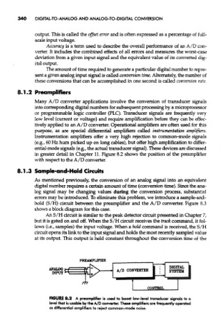
in greater detail in Chapter 11. Figure 8.2 shows the position of the preamplifier
with respect to the A/D converter.
8.1.3 Sample-and-Hold Circuits
As mentioned previously, the conversion of an analog signal into an equivalent
digital number requires a certain amount of time (conversion time). Since the ana-
log signal may be changing values during the conversion process, substantial
errors may be introduced. To eliminate this problem, we introduce a sample-and-
hold (S/H) circuit between the preamplifier and the A/D converter. Figure 8.3
shows a block diagram for this case.
An S/H circuit is similar to the peak detector circuit presented in Chapter 7,
but it is gated on and off. When the S/H circuit receives the track command, it fol-
lows (i.e., samples) the input voltage. When a hold command is received, the S/H
circuit opens its link to the input signal and holds the most recently sampled value
at its output. This output is held constant throughout the conversion time of the
FIGURE 8.2 A preamplifier is used to boost low-level transducer signals to a
level that is usable by the A/D converter. These amplifiers are frequently operated
as differential amplifiers to reject common-mode noise.