
Page 366 - Op Amps Design, Applications, and Troubleshooting
P. 366
D/A and A/D Conversion Fundamentals 343
This approach to system design can make it possible to use higher-
performance (i.e., more expensive) sample-and-hold and A/D converter circuits
by requiring only one such circuit for multiple inputs.
Multiplexers are available as integrated circuits. The AD7506 manufactured
by Analog Devices, Inc., is a 16-channel device designed to select 1 of 16 analog
input signals and connect it through to a single analog output.
8.1.5 Digital-to-Analog Converters
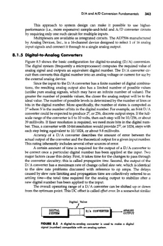
Figure 8.5 shows the basic configuration for digital-to-analog (D/A) conversion.
The digital system (frequently a microprocessor) computes the required value of
analog signal and outputs an equivalent digital number. The D/A converter cir-
cuit then converts this digital number into an analog voltage or current for use by
the external analog device.
Since the input to the D/A converter has a finite number of digital combina-
tions, the resulting analog output also has a limited number of possible values
(unlike pure analog signals, which may have an infinite number of values). The
greater the number of possible values, the closer the analog output will be to the
ideal value. The number of possible levels is determined by the number of lines or
bits in the digital number. More specifically, the number of states is computed as
N
2 where N is the number of bits in the digital number. For example, an 8-bit D/A
8
converter could be expected to produce 2 , or 256, discrete output steps. If the full-
scale range of the converter is 0 to 10 volts, then each step will be 10/256, or about
39 millivolts. If finer resolution is required, we need more bits in the digital num-
10
ber. Thus, a converter with 10-bit resolution would provide 2 , or 1024, steps with
each step being equivalent to 10/1024, or about 9.8 millivolts.
Accuracy of a D/A converter describes the amount of error between the
actual output of the converter and the theoretical output for a given input number.
This rating inherently includes several other sources of error.
A certain amount of time is required for the output of a D/A converter to
be correct once a particular digital number has been applied at the input. Two
major factors cause this delay. First, it takes time for the changes to pass through
the converter circuitry; this is called propagation time. Second, the output of the
D/A converter has a maximum rate of change called slew rate, which is identical
to the slew rate problems discussed with reference to op amps. The delays
caused by slew rate limiting and propagation time are collectively referred to as
settling time—the total time required for the analog output to stabilize after a
new digital number has been applied to the input.
The overall operating range of a D/A converter can be shifted up or down
from the optimum point. This DC offset is called offset error. In a somewhat similar
FIGURE 8*5 A digital-to-analog converter is used to make a digital
signal (number) compatible with an analog system.