
Page 370 - Op Amps Design, Applications, and Troubleshooting
P. 370
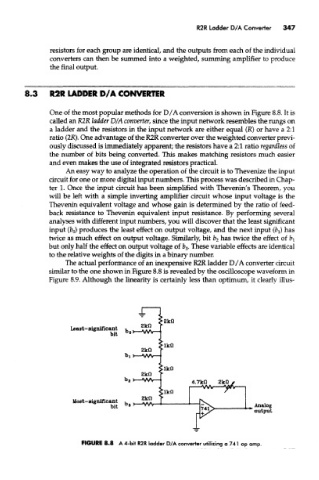
R2R Ladder D/A Converter  347


               resistors for each group are identical, and the outputs from each of the individual
               converters can then be summed into a weighted, summing amplifier to produce
               the final output.


        8.3    R2R LADDER D/A CONVERTER

               One of the most popular methods for D/A conversion is shown in Figure 8.8. It is
               called an R2R ladder D/A converter, since the input network resembles the rungs on
               a ladder and the resistors in the input network are either equal (JR) or have a 2:1
               ratio (2K). One advantage of the R2R converter over the weighted converter previ-
               ously discussed is immediately apparent; the resistors have a 2:1 ratio regardless of
               the number of bits being converted. This makes matching resistors much easier
               and even makes the use of integrated resistors practical.
                    An easy way to analyze the operation of tike circuit is to Thevenize the input
               circuit for one or more digital input numbers. This process was described in Chap-
               ter 1. Once the input circuit has been simplified with Thevenin's Theorem, you
               will be left with a simple inverting amplifier circuit whose input voltage is the
               Thevenin equivalent voltage and whose gain is determined by the ratio of feed-
               back resistance to Thevenin equivalent input resistance. By performing several
               analyses with different input numbers, you will discover that the least significant
               input (b 0) produces the least effect on output voltage, and the next input (fej) has
               twice as much effect on output voltage. Similarly, bit b 2 has twice the effect of fe t
               but only half the effect on output voltage of b$. These variable effects are identical
               to the relative weights of the digits in a binary number.
                    The actual performance of an inexpensive R2R ladder D/A converter circuit
               similar to the one shown in Figure 8.8 is revealed by the oscilloscope waveform in
               Figure 8.9. Although the linearity is certainly less than optimum, it clearly illus-


                        FIGURE 8.8 A 4-bit R2R ladder D/A converter utilizing a 741 op amp.