
Page 369 - Op Amps Design, Applications, and Troubleshooting
P. 369
346 DIGHAL-TO-ANALOG AND ANALOG-TO-DIGITAL CONVERSION
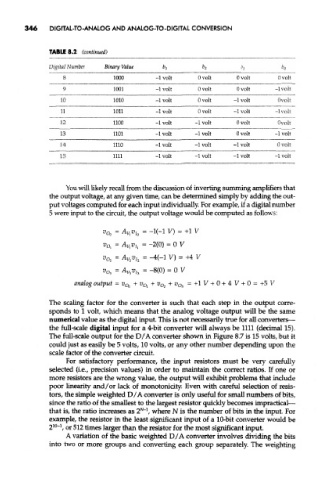
TABLE 8.2 (continued)
Digital Number Binary Value h b 2 bi bo
8 1000 -1 volt Ovolt Ovolt 0 volt
9 1001 -1 volt Ovolt Ovolt -1 volt
10 1010 -1 volt Ovolt -1 volt 0 volt
11 1011 -1 volt 0 volt -1 volt -1 volt
12 1100 -1 volt -1 volt Ovolt 0 volt
13 1101 -1 volt -1 volt Ovolt -1 volt
14 1110 -1 volt -1 volt -1 volt 0 volt
15 1111 -1 volt -1 volt -1 volt -1 volt
You will likely recall from the discussion of inverting summing amplifiers that
the output voltage, at any given time, can be determined simply by adding the out-
put voltages computed for each input individually. For example, if a digital number
5 were input to the circuit, the output voltage would be computed as follows:
^o 0 = ^Vie = -1(-1 V) = +1 V
v* = A Vlv h = -2(0) = 0 V
v 02 = A V2v h = -4(~1 V) = +4 V
v 03 = A Vav h = -8(0) = 0 V
analog output = v O(, + v Ol + v O2 + v Oz = +1 V + 0 + 4 V + 0 = +5 V
The scaling factor for the converter is such that each step in the output corre-
sponds to 1 volt, which means that the analog voltage output will be the same
numerical value as the digital input. This is not necessarily true for all converters—
the full-scale digital input for a 4-bit converter will always be 1111 (decimal 15).
The full-scale output for the D/A converter shown in Figure 8.7 is 15 volts, but it
could just as easily be 5 volts, 10 volts, or any other number depending upon the
scale factor of the converter circuit.
For satisfactory performance, the input resistors must be very carefully
selected (i.e., precision values) in order to maintain the correct ratios. If one or
more resistors are the wrong value, the output will exhibit problems that include
poor linearity and/or lack of monotonicity. Even with careful selection of resis-
tors, the simple weighted D/A converter is only useful for small numbers of bits,
since the ratio of the smallest to the largest resistor quickly becomes impractical—
N-1
that is, the ratio increases as 2 , where N is the number of bits in the input. For
example, the resistor in the least significant input of a 10-bit converter would be
10 1
2 ~ , or 512 times larger than the resistor for the most significant input.
A variation of the basic weighted D/A converter involves dividing the bits
into two or more groups and converting each group separately. The weighting