
Page 368 - Op Amps Design, Applications, and Troubleshooting
P. 368
Weighted D/A Converter 345
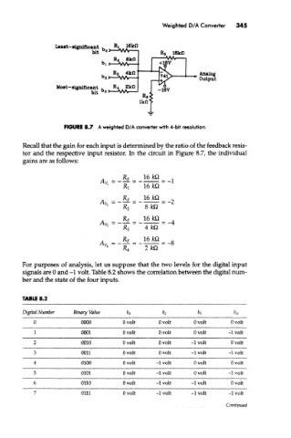
FIGURE 8.7 A weighted D/A converter with 4-bit resolution.
Recall that the gain for each input is determined by the ratio of the feedback resis-
tor and the respective input resistor. In the circuit in Figure 8.7, the individual
gains are as follows:
For purposes of analysis, let us suppose that the two levels for the digital input
signals are 0 and -1 volt. Table 8.2 shows the correlation between the digital num-
ber and the state of the four inputs.
TABLE 8.2
Digital Number Binary Value &2 fa, b 0
b 3
0 0000 Ovolt Ovolt Ovolt Ovolt
1 0001 Ovolt Ovolt Ovolt -1 volt
2 0010 Ovolt Ovolt -1 volt Ovolt
3 0011 Ovolt Ovolt -1 volt -1 volt
4 0100 Ovolt -1 volt Ovolt Ovolt
5 0101 Ovolt -1 volt Ovolt -1 volt
6 0110 Ovolt -1 volt -1 volt Ovolt
7 0111 Ovoit -1 volt -1 volt -1 volt
Continued