
Page 375 - Op Amps Design, Applications, and Troubleshooting
P. 375
Tracking A/D Converter 351
TABLE 8.3
Voltage Range Comparator States Digital Result
0 < %, < 1.25 Volts 0000000 000
1.25 Volts < Oflv <2.5 Volts 0000001 001
2.5 Volts < t> /N < 3.75 Volts 0000011 010
3,75 Volts < v, N < 5 Volts 0000111 Oil
5 Volts < V IN < 6.25 Volts 0001111 100
6.25 Volts < WI N < 7.5 Volts 0011111 101
7.5 Volts < V M < 8.75 Volts 0111111 110
8.75 Volts < %, < 10 Volts 1111111 111
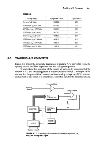
8.5 TRACKING A/D CONVERTER
Figure 8.11 shows the schematic diagram of a tracking A/D converter. Here, the
op amp plays a small but important role as a voltage comparator.
To understand the operation of the circuit, let us begin by assuming that the
counter is at 0 and the analog input is at some positive voltage. The output of the
counter (0 at the present time) is converted to an analog voltage by a D/A converter
and applied to one input of a comparator. The other input is the amplified analog
FIGURE 8.11 A tracking A/D converter will continuously follow (i.e.
track) the analog input signal.