
Page 378 - Op Amps Design, Applications, and Troubleshooting
P. 378
354 DJGITAL-TO-ANALOG AND ANALOG-TO-DIGITAL CONVERSION
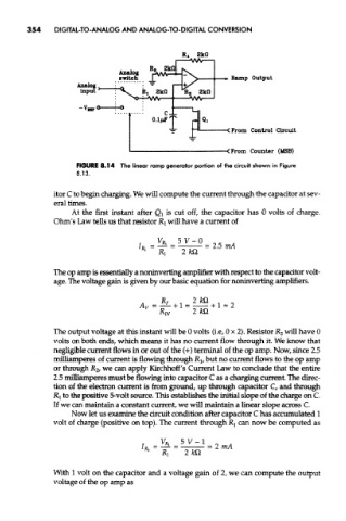
FIGURE 8.14 The linear ramp generator portion of the circuit shown in Figure
8.13.
itor C to begin charging. We will compute the current through the capacitor at sev-
eral times.
At the first instant after Qi is cut off, the capacitor has 0 volts of charge.
Ohm's Law tells us that resistor RI will have a current of
The op amp is essentially a noninverting amplifier with respect to the capacitor volt-
age. The voltage gain is given by our basic equation for noninverting amplifiers.
The output voltage at this instant will be 0 volts (i.e, 0x2). Resistor R 2 will have 0
volts on both ends, which means it has no current flow through it. We know that
negligible current flows in or out of the (+) terminal of the op amp. Now, since 2.5
milliamperes of current is flowing through RI, but no current flows to the op amp
or through R& we can apply Kirchhoff's Current Law to conclude that the entire
2.5 milliamperes must be flowing into capacitor C as a charging current. The direc-
tion of the electron current is from ground, up through capacitor C, and through
RI to the positive 5-volt source. This establishes the initial slope of the charge on C.
If we can maintain a constant current, we will maintain a linear slope across C.
Now let us examine the circuit condition after capacitor C has accumulated 1
volt of charge (positive on top). The current through R} can now be computed as
With 1 volt on the capacitor and a voltage gain of 2, we can compute the output
voltage of the op amp as