
Page 376 - Op Amps Design, Applications, and Troubleshooting
P. 376
352 DIGITAL-TO-ANALOG AND ANALOG-TO-DIGITAL CONVERSION
input signal. Under the given conditions, the output of the comparator will be low.
The control unit interprets this comparator output to mean that the counter output
is lower than the analog input, so the counter is allowed to increment.
This situation continues on each subsequent clock pulse until the counter
has incremented to a value that exceeds the analog input voltage. When this point
is reached, the output of the D/A will be higher than the analog input voltage,
causing the comparator output to go to a high level. The control unit interprets
this to mean that the counter has exceeded the input and directs the counter to
begin counting down.
As the counter decrements, the output of the D/A becomes less. As soon as
the D/A output falls below the analog input, the output of the comparator
switches low again and causes the counter to start incrementing once more. Thus,
as the input changes the counter automatically tracks it.
Every time the comparator changes state, the control unit transfers the
counter value to a latch where it is accessible to other circuitry. This method is sim-
ple and inexpensive, but it is not particularly fast (especially for large input
changes). For example, let us assume that the clock is operating at 20 megahertz
and the converter is designed to provide a 16-bit output. If the input signal makes
a small (equivalent of 1 bit) change, then it will take the circuit 1 /20 megahertz, or
50 nanoseconds, to provide a valid output. However, if the input makes a full-
16
range step change, it takes the converter (1/20 MHz) x 2 , or 3.28 milliseconds, to
provide a valid result. This converter is best suited for either slow signals or sig-
nals that make only small changes at any given time.
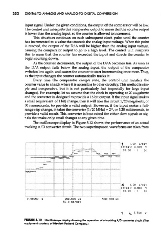
The oscilloscope display in Figure 8.12 shows the performance of an actual
tracking A/D converter circuit. The two superimposed waveforms are taken from
FIGURE 8.12 Oscilloscope display showing the operation of a tracking A/D converter circuit. (Test
equipment courtesy of Hewlett-Packard Company.)