
Page 381 - Op Amps Design, Applications, and Troubleshooting
P. 381
Successive Approximation A/D Converter 357
linearly discharge to 0 volts. The slope of t 2 is fixed and is determined by the neg-
ative reference, so time t 2 is variable and dependent on the value of voltage accu-
mulated on capacitor C during time ^. This voltage, of course, was determined by
the value of analog input voltage. Since time t 2 is dependent on the value of ana-
log input voltage, the number of counts registered in the counter will also be a
function of the analog input voltage.
Figure 8.15 contrasts the results of two different analog input voltages. V a is
the result of a higher input voltage. It takes a certain amount of time (f 2) to dis-
charge the capacitor and stop the counter. A lower input voltage (V C2) charges C to
a lower voltage during the fixed time period t lr so the discharge time (£ 3) is shorter
and the counter will have a smaller count. The final converted result appears in
the counter and ignores the MSB.
The dual-slope A/D conversion method is very popular in applications that
do not require high-speed operation. It has distinct advantages that include high
immunity to component tolerances, component drifts, and noise. This increased
immunity stems from the fact that errors introduced during the positive slope will
be largely offset by similar errors during the negative slope. The circuit offers total
rejection of noise signals that are even multiples of the time period t lf since the net
effect of a full cycle of noise is 0.
Complete dual-slope converter systems are available in integrated form. A
common application is for digital voltmeters. The analog portion of such a system is
manufactured by National Semiconductor Corporation in the form of an LF12300
integrated circuit. Analog Devices has a patented improvement on the basic dual-
slope converter called Quad-Slope conversion. This is used in the AD7550 13-bit
A/D converter manufactured by Analog Devices.
8.7 SUCCESSIVE APPROXIMATION A/D CONVERTER
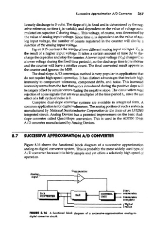
Figure 8.16 shows the functional block diagram of a successive approximation
analog-to-digital converter system. This is probably the most widely used type of
A/D converter because it is fairly simple and yet offers a relatively high speed of
operation.
FIGURE 8.16 A functional block diagram of a successive-approximation analog-k>
digital converter circuit.