
Page 385 - Op Amps Design, Applications, and Troubleshooting
P. 385
Adder 361
FIGURE 9.1 A noninverting adder
circuit sums the instantaneous voltage
at several inputs.
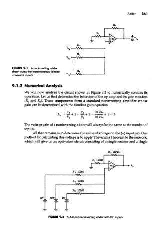
9.1.2 Numerical Analysis
We will now analyze the circuit shown in Figure 9.2 to numerically confirm its
operation. Let us first determine the behavior of the op amp and its gain resistors
(Rj and JR 2)- These components form a standard noninverting amplifier whose
gain can be determined with the familiar gain equation.
The voltage gain of a noninverting adder will always be the same as the number of
inputs.
All that remains is to determine the value of voltage on the (+) input pin. One
method for calculating this voltage is to apply Thevenin's Theorem to the network,
which will give us an equivalent circuit consisting of a single resistor and a single
FIGURE 9.2 A 3-input noninverting adder with DC inputs.