
Page 386 - Op Amps Design, Applications, and Troubleshooting
P. 386
362 ARITHMETIC FUNCTION CIRCUITS
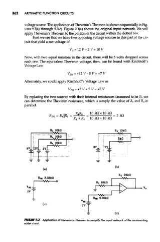
voltage source. The application of Thevenin's Theorem is shown sequentially in Fig-
ures 93(a) through 9.3(c). Figure 9.3(a) shows the original input network. We will
apply Thevenin's Theorem to the portion of the circuit within the dotted box.
First we see that we have two opposing voltage sources in this part of the cir-
cuit that yield a net voltage of
Now, with two equal resistors in the circuit, there will be 5 volts dropped across
each one. The equivalent Thevenin voltage, then, can be found with Kirchhoff 's
Voltage Law.
Alternately, we could apply Kirchhoff's Voltage Law as
By replacing the two sources with their internal resistances (assumed to be 0), we
can determine the Thevenin resistance, which is simply the value of R 5 and R 4 in
parallel.
FIGURE 9.3 Application of Thevenin's Theorem to simplify the input network of the noninverting
adder circuit.