
Page 391 - Op Amps Design, Applications, and Troubleshooting
P. 391
Subtracter 367
According to the Superposition Theorem, the output should be the net result
of the two individual input signals. That is, the output voltage will be +V A ~ V B.
Thus, we can see that the circuit does indeed perform the function of a subtracter
circuit,
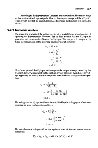
9,2.2 Numerical Analysis
The numerical analysis of the subtracter circuit is straightforward and consists of
applying the Superposition Theorem. Let us first assume that the V A input is
grounded and compute the effects of the V B input. The output will be equal to V B
times the voltage gain of the inverting amplifier circuit, which is
Now let us ground the V B input and compute the output voltage caused by the
V A input. First, V A is reduced by the voltage divider action of R 3 and K 4. The volt-
age appearing on the (+) input is computed with the basic voltage divider equa-
tion.
The voltage on the (+) input will now be amplified by the voltage gain of the non-
inverting op amp configuration, which is
The actual output voltage will be the algebraic sum of the two partial outputs
computed: