
Page 393 - Op Amps Design, Applications, and Troubleshooting
P. 393
Subtracter 369
cations can be found by applying Equation (2.11). The maximum output voltage
change will be 10 volts and the frequency may be as high as 10 kilohertz.
slew rate = 7r/b 0(max) = 3.14 x 10 kHz x 10 V = 0.314 V//E
This is within the range of the standard 741 op amp. The unity gain frequency
required to meet the bandwidth requirements can be estimated with Equation
(2.22). In the present case, the minimum unity gain frequency is computed as
which is well below the 1.0-megahertz unity gain frequency of the standard 741,
Let us use this device in our design.
There are several other nonideal op amp parameters that could play a signif-
icant role in op amp selection. These factors are discussed in Chapter 10.
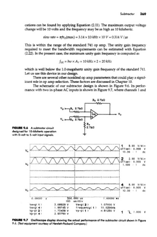
The schematic of our subtracter design is shown in Figure 9.6. Its perfor-
mance with two in-phase AC inputs is shown in Figure 9.7, where channels 1 and
FIGURE 9.6 A subtracter circuit
designed for 10-kilohertz operation
with 0-voft to 5-volt input signals.
FIGURE 9.7 Oscilloscope display showing the actual performance of the subtracter circuit shown in Figure
9.6. (Test equipment courtesy of Hewlett-Packard Company.)