
Page 397 - Op Amps Design, Applications, and Troubleshooting
P. 397
Absolute Value Circuit 373
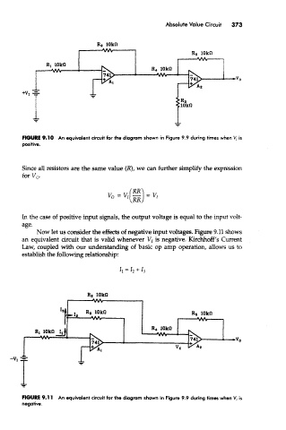
FIGURE 9.10 An equivalent circuit for the diagram shown in Figure 9.9 during times when V, is
positive.
Since all resistors are the same value (R), we can further simplify the expression
£~~ t7
In the case of positive input signals, the output voltage is equal to the input volt-
age.
Now let us consider the effects of negative input voltages. Figure 9.11 shows
an equivalent circuit that is valid whenever V/ is negative. Kirchhoff's Current
Law, coupled with our understanding of basic op amp operation, allows us to
establish the following relationship:
FIGURE 9.11 An equivalent circuit for the diagram shown in Figure 9.9 during times when V, is
negative.