
Page 400 - Op Amps Design, Applications, and Troubleshooting
P. 400
376 ARITHMETIC FUNCTION CIRCUITS
This slew rate exceeds the capability of the standard 741, but falls within the 10-
volts-per-microsecond slew rate capability of the MC1741SC. Let us utilize this
device in our design. It should be noted that in critical applications several addi-
tional nonideal op amp characteristics should be evaluated before a particular op
amp is selected. These characteristics are discussed in Chapter 10.
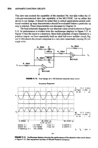
The final schematic diagram for our absolute value circuit is shown in Figure
9.12. Its performance is evident from the oscilloscope displays in Figure 9.13. In
Figure 9.13(a) the input is a sinewave. Since both polarities of input translate to a
positive output, we have essentially built an ideal full-wave rectifier circuit. Fig-
ure 9,13(b) shows the circuit's response to a very slow (essentially varying DC) tri-
angle wave.
FIGURE 9.12 Final design of a 100-kilohertz absolute value circuit.
Sinewave Response
FIOURI 9.13 Oscilloscope displays showing the performance of the absolute value circuit shown
in Figure 9.12. {Test equipment courtesy of Hewlett-Packard Company.)