
Page 401 - Op Amps Design, Applications, and Troubleshooting
P. 401
Sign Changing Circuit 377
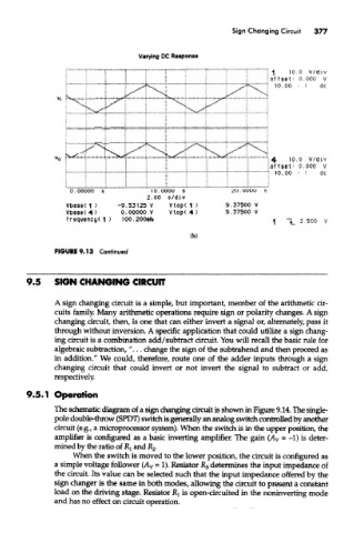
Varying DC Response
9.5 SIGN CHANGING CIRCUIT
A sign changing circuit is a simple, but important, member of the arithmetic cir-
cuits family. Many arithmetic operations require sign or polarity changes. A sign
changing circuit, then, is one that can either invert a signal or, alternately, pass it
through without inversion. A specific application that could utilize a sign chang-
ing circuit is a combination add/subtract circuit. You will recall the basic rule for
algebraic subtraction, "... change the sign of the subtrahend and then proceed as
in addition." We could, therefore, route one of the adder inputs through a sign
changing circuit that could invert or not invert the signal to subtract or add,
respectively.
9.5.1 Operation
The schematic diagram of a sign changing circuit is shown in Figure 9.14. The single-
pole double-throw (SPDT) switch is generally an analog switch controlled by another
circuit (e.g., a microprocessor system). When the switch is in the upper position, the
amplifier is configured as a basic inverting amplifier. The gain (A v - -1) is deter-
mined by the ratio of JRj and R 2.
When the switch is moved to the lower position, the circuit is configured as
a simple voltage follower (A v = 1). Resistor R 3 determines the input impedance of
the circuit. Its value can be selected such that the input impedance offered by the
sign changer is the same in both modes, allowing the circuit to present a constant
load on the driving stage. Resistor JRj is open-circuited in the noninvertmg mode
and has no effect on circuit operation.