
Page 403 - Op Amps Design, Applications, and Troubleshooting
P. 403
Sign Changing Circuit 379
slew rate = nfV o(ma\) = 3.14 x 8.5 kHz x 26 V = 0.694 V/ps
The bandwidth specification can be satisfied by most any op amp. The required
slew rate, however, exceeds the 0.5-volts-per-microsecond rating for the standard
741. Let us plan to use an MC1741SC device, which satisfies both bandwidth and
slew rate requirements.
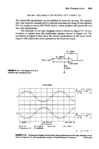
The schematic of our sign changing circuit is shown in Figure 9.15. Its per-
formance is evident from the oscilloscope displays shown in Figure 9.16. The
waveforms in Figure 9.16{a) show the circuit's performance in the invert mode.
Figure 9.16(b) shows the circuit operated in the noninvert mode.
FIGURE 9.15 Final design of an 8.5-
kiiohertz sign changing circuit.
FIGURE 9.16 Oscilloscope displays showing the actual performance of the sign-changing circuit
shown in Figure 9.T5. (Test equipment courtesy of Hewlett-Packard Company.) (continued)