
Page 408 - Op Amps Design, Applications, and Troubleshooting
P. 408
384 NONIDEAL OP AMP CHARACTERISTICS
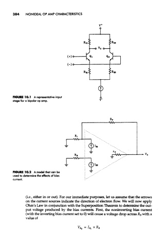
FIGURE 10.1 A representative input
stage for a bipolar op amp.
FIGURE 10.2 A model that can be
used to determine the effects of bias
current.
(i.e., either in or out). For our immediate purposes, let us assume that the arrows
on the current sources indicate the direction of electron flow. We will now apply
Ohm's Law in conjunction with the Superposition Theorem to determine the out-
put voltage produced by the bias currents. First, the noninverting bias current
(with the inverting bias current set to 0) will cause a voltage drop across R B with a
value of