
Page 390 - Op Amps Design, Applications, and Troubleshooting
P. 390
366 ARITHMETIC FUNCTION CIRCUITS
TABLE 9.1
Input Voltages Output Voltage
v, ^2 V 3 V 4 Ideal Actual
-15.09 volte 4.37 volts 0 volts 0 volts 10.72 volts 10.8 volts
-8,1 volts -2.0 volts 6.6 volts 2.7 volts -0.8 volts -0.74 volts
1.52 volts 0 volts -3.1 volts -1.49 volts -3.07 volts -2,98 vote
9.2 SUBTRACTOR
Another circuit that performs a fundamental arithmetic operation is the subtrac-
ter. This circuit generally has two inputs (either AC or DC) and produces an out-
put voltage that is equal to the instantaneous difference between the two input
signals. Of course, this is the very definition of a difference amplifier, which is
another name for the subtracter circuit.
9.2.1 Operation
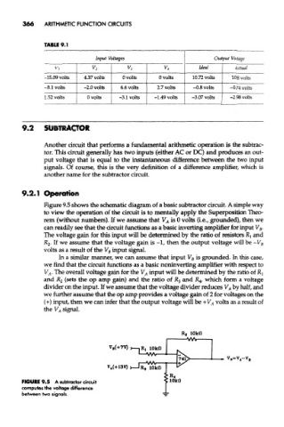
Figure 9.5 shows the schematic diagram of a basic subtracter circuit. A simple way
to view the operation of the circuit is to mentally apply the Superposition Theo-
rem (without numbers). If we assume that V A is 0 volts (i.e., grounded), then we
can readily see that the circuit functions as a basic inverting amplifier for input V B.
The voltage gain for this input will be determined by the ratio of resistors R] and
R 2- If we assume that the voltage gain is -1, then the output voltage will be -V B
volts as a result of the V B input signal.
In a similar manner, we can assume that input V B is grounded. In this case,
we find that the circuit functions as a basic noninverting amplifier with respect to
V A. The overall voltage gain for the V A input will be determined by the ratio of RI
and R 2 (sets the op amp gain) and the ratio of R 3 and £4, which form a voltage
divider on the input. If we assume that the voltage divider reduces V A by half, and
we further assume that the op amp provides a voltage gain of 2 for voltages on the
(+) input, then we can infer that the output voltage will be +V A volts as a result of
the V A signal.
FIGURE 9.5 A subtracter circuit
computes the voltage difference
between two signals.