
Page 380 - Op Amps Design, Applications, and Troubleshooting
P. 380
356 DIG1TAL-TO-ANALOG AND ANALOG-TO-DIGITAL CONVERSION
Now, let us analyze the overall operation of the dual-ramp A/D converter
shown in Figure 8.13. The input voltage to the ramp is switch-selected as either the
analog voltage to be converted (positive) or a fixed, negative reference voltage,
Recall that the input voltage to the ramp circuit determines the slope of the ramp.
The position of the analog switch is controlled by the state of the most significant
bit (MSB) of a counter. More specifically, if the MSB is low, then the switch will con-
nect the analog input to the ramp generator. If the MSB of the counter is high, then
the switch connects the negative reference voltage to the ramp generator input.
The counter is enabled (i.e., allowed to count) as long as the output of the
ramp generator is positive. That is, as long as the ramp is above ground, the out-
put of the comparator will be low and will enable the counter. If the ramp ever
goes below ground, then the output of the comparator will switch to a high state
and disable the counter.
The control circuit provides the overall timing of circuit operation, On
receipt of a start conversion signal from the main control system (generally a micro-
processor), the control unit will reset the counter to 0 and release (i.e., cut off) Qj.
With the counter reset, the MSB will be 0 and the analog switch will be connecting
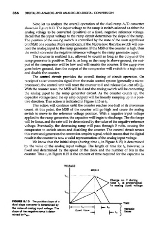
the analog input to the ramp generator circuit. As the counter counts up, the
capacitor voltage (and the op amp output) will be linearly ramping up in a posi-
tive direction. This action is indicated in Figure 8.15 as t\.
This action will continue until the counter reaches one-half of its maximum
count. At this point, the MSB of the counter will go high and cause the analog
switch to move to the reference voltage position. With a negative input voltage
appEed to the ramp generator, the capacitor will begin to discharge. The discharge
will be linear, and the rate will be determined by the value of the negative reference
voltage. Eventually, the decreasing ramp wiU pass through 0 volts, causing the
comparator to switch states and disabling the counter. The control circuit senses
this event and generates the conversion complete signal, which means that the digital
result in the counter is now a valid representation of the analog input voltage.
We know that the initial slope (during time ^ in Figure 8.15) is determined
by the value of the analog input voltage. The length of time for t lf however, is
fixed and determined by the speed of the clock and the number of bite in the
counter. Time t 2 in Figure 8.15 is the amount of time required for the capacitor to
FIGURE 8.15 The positive slope of a
dual-slope converter is determined by
the value of analog input voltage. The
slope of the negative ramp is deter-
mined by Vj) EF.