
Page 76 - Op Amps Design, Applications, and Troubleshooting
P. 76
Noninverting Amplifier 59
AAAr
--1
I—vw
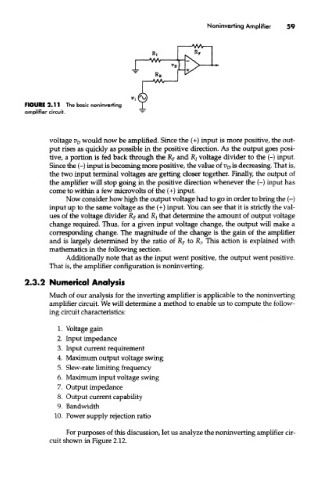
FiGURE 2.11 The basic noninverting
amplifier circuit.
voltage V D would now be amplified. Since the (+) input is more positive, the out-
put rises as quickly as possible in the positive direction. As the output goes posi-
tive, a portion is fed back through the R F and R/ voltage divider to the (-) input.
Since the (-) input is becoming more positive, the value of V D is decreasing. That is,
the two input terminal voltages are getting closer together. Finally, the output of
the amplifier will stop going in the positive direction whenever the (-) input has
come to within a few microvolts of the (+) input.
Now consider how high the output voltage had to go in order to bring the (-)
input up to the same voltage as the (+) input. You can see that it is strictly the val-
ues of the voltage divider R F and R z that determine the amount of output voltage
change required. Thus, for a given input voltage change, the output will make a
corresponding change. The magnitude of the change is the gain of the amplifier
and is largely determined by the ratio of R F to R/. This action is explained with
mathematics in the following section.
Additionally note that as the input went positive, the output went positive.
That is, the amplifier configuration is noninverting.
2.3.2 Numerical Analysis
Much of our analysis for the inverting amplifier is applicable to the noninverting
amplifier circuit. We will determine a method to enable us to compute the follow-
ing circuit characteristics:
1. Voltage gain
2. Input impedance
3. Input current requirement
4. Maximum output voltage swing
5. Slew-rate limiting frequency
6. Maximum input voltage swing
7. Output impedance
8. Output current capability
9. Bandwidth
10. Power supply rejection ratio
For purposes of this discussion, let us analyze the noninverting amplifier cir-
cuit shown in Figure 2.12.