
Page 79 - Op Amps Design, Applications, and Troubleshooting
P. 79
62 AMPLIFIERS
Input Impedance. The input impedance of the noninverting amplifier circuit
(refer to Figure 2.12) is essentially equal to the input impedance of the (+) input
terminal of the op amp modified by the feedback effects. That is, the only current
leaving the source must flow into or out of the op amp as bias current for the (+)
input. The manufacturer's data sheet for a 741 is shown in Appendix 1. It indicates
that the input resistance is at least 0.3 megohms and is typically about 2.0
megohms. Recall that this is the effective resistance between the two op amp
inputs. By considering the output impedance to be near 0, we can sketch the
equivalent circuit shown in Figure 2.13(a).
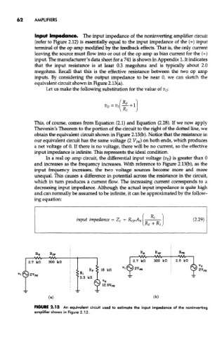
Let us make the following substitution for the value of v 0:
This, of course, comes from Equation (2.1) and Equation (2.28). If we now apply
Thevenin's Theorem to the portion of the circuit to the right of the dotted line, we
obtain the equivalent circuit shown in Figure 2.13(b). Notice that the resistance in
our equivalent circuit has the same voltage (2 V PK) on both ends, which produces
a net voltage of 0. If there is no voltage, there will be no current, so the effective
input impedance is infinite. This represents the ideal condition.
In a real op amp circuit, the differential input voltage (i? D) is greater than 0
and increases as the frequency increases. With reference to Figure 2,13(b), as the
input frequency increases, the two voltage sources become more and more
unequal. This causes a difference in potential across the resistance in the circuit,
which in turn produces a current flow. The increasing current corresponds to a
decreasing input impedance. Although the actual input impedance is quite high
and can normally be assumed to be infinite, it can be approximated by the follow-
ing equation:
FIGURE 2.13 An equivalent circuit used to estimate the input impedance of the noninverting
amplifier shown in Figure 2.12.