
Page 77 - Op Amps Design, Applications, and Troubleshooting
P. 77
60 AMPLIFIERS
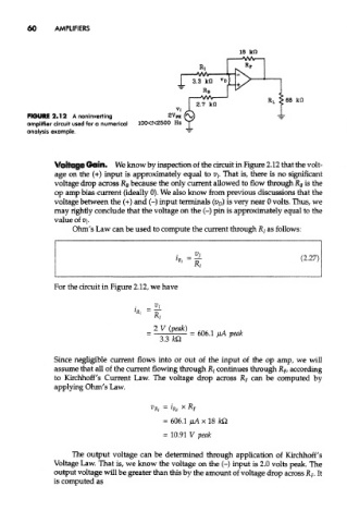
FIGURE 2.12 A noninverting
amplifier circuit used for a numerical
analysis example.
Voltage Gain. We know by inspection of the circuit in Figure 2.12 that the volt-
age on the (+) input is approximately equal to v t. That is, there is no significant
voltage drop across Rg because the only current allowed to flow through R B is the
op amp bias current (ideally 0). We also know from previous discussions that the
voltage between the (+) and (-) input terminals (V D) is very near 0 volts. Thus, we
may rightly conclude that the voltage on the (-) pin is approximately equal to the
value of Vj.
Ohm's Law can be used to compute the current through R/ as follows:
For the circuit in Figure 2.12, we have
Since negligible current flows into or out of the input of the op amp, we will
assume that all of the current flowing through Rj continues through R F, according
to Kirchhoff's Current Law. The voltage drop across R F can be computed by
applying Ohm's Law.
The output voltage can be determined through application of Kirchhoff's
Voltage Law. That is, we know the voltage on the (-) input is 2.0 volts peak. The
output voltage will be greater than this by the amount of voltage drop across R F. It
is computed as