
Page 105 - Optofluidics Fundamentals, Devices, and Applications
P. 105
86 Cha pte r F i v e
Y-branched
waveguide Microscope
objective
PDMS
cell
Polystyrene
particles in
water
Output
Fiber
Substrate
(a)
Time 150000 ms
60
50
y position (μm) 40
30
20
10
0
0 50 100 150 200 250 300 350 400
x position (μm)
(b)
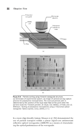
FIGURE 5-4 Particle sorting using Y-branch waveguide structure.
(a) Schematic of experimental system. (b) Image of particle-sorting capture
process for polystyrene microparticles. The eventual particle path is
determined by the position of the input laser fi ber at the point when the
particle nears the Y-branch junction. (K. Grujic, O.G. Helleso, J.P. Hole, and J.S.
Wilkinson, “Sorting of polystyrene microspheres using a Y-branched optical
waveguide,” Optics Express, 13(1), (2005), 1–7.)
In a more chip-friendly format, Measor et al. [56] demonstrated the
use of particle transport within a planar liquid-core antiresonant
reflective optical waveguides (ARROW) as a means of characteriz-
ing the optical performance of the waveguide.