
Page 260 - Optofluidics Fundamentals, Devices, and Applications
P. 260
Lens
Focused laser
(a)
(b)
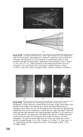
FIGURE 9-25 A planar spherical lens. Laser light comes from the right-hand
side and is focused. Good agreement between experiment and simulation is
achieved. Nanoparticles are incorporated as scattering centers to help
visualize the light focusing effect. (Reprinted with permission from J. Godin,
V. Lien, and Y. H. Lo, “Demonstration of two-dimensional fl uidic lens for
integration into microfl uidic fl ow cytometers,” Applied Physics Letters,
vol. 89, p. 061106, 2006. Copyright 2006, American Institute of Physics.)
Filling channel
Lens Waveguide
Center
Blocking bar portion
Aperture
of light
(a) (b) (c)
FIGURE 9-26 (a) Structure of a blocking bar between a lens and an exit
waveguide. A fi lling channel is located below the plane of light travel enters from
the top of the image. The blocking bar is above the fi lling channel and is
indicated by the dotted box. (b) The blocking bar demonstrates the light-blocking
capabilities that can be employed in on-chip devices. Light blocking is critical for
reducing stray light collection and improving signal resolution. (c) An aperture in
an on-chip device. The apertures is denoted in the red box. The fi lling channel
connects the two sides of the aperture from below the plane of the slab
waveguide. The aperture blocks light from the sides, but allows the central
portion to travel through. (S. H. Cho, J. Godin, C. H. Chen, F. S. Tsai, and Y. H.
Lo, “Microfl uidic photonic integrated circuits,” Proceedings of SPIE, 7135,
71350M, 2008.)
234