
Page 268 - Optofluidics Fundamentals, Devices, and Applications
P. 268
242 Cha pte r T e n
Dye laser
light Pump laser
z light
y
Top x
mirror
Dye 1 mm 20 μm
flow
Fluid channel
Bottom Fluid in
mirror Light out
(a)
Pump light
Resonator
Outlet
PDMS
(waveguide)
chip Light out
Inlet Bragg grating Microfluidic channel Waveguides Fluid out
Dye solution Laser output 1 cm
(c) (b)
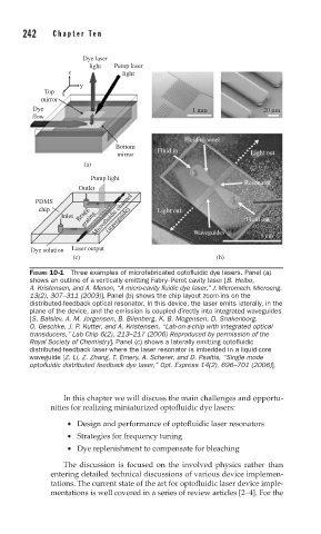
FIGURE 10-1 Three examples of microfabricated optofluidic dye lasers. Panel (a)
shows an outline of a vertically emitting Fabry–Perot cavity laser [B. Helbo,
A. Kristensen, and A. Menon, “A micro-cavity fluidic dye laser,” J. Micromech. Microeng.
13(2), 307–311 (2003)]. Panel (b) shows the chip layout zoom-ins on the
distributed-feedback optical resonator. In this device, the laser emits laterally, in the
plane of the device, and the emission is coupled directly into integrated waveguides
[S. Balslev, A. M. Jorgensen, B. Bilenberg, K. B. Mogensen, D. Snakenborg,
O. Geschke, J. P. Kutter, and A. Kristensen, “Lab-on-a-chip with integrated optical
transducers,” Lab Chip 6(2), 213–217 (2006) Reproduced by permission of the
Royal Society of Chemistry]. Panel (c) shows a laterally emitting optofluidic
distributed-feedback laser where the laser resonator is imbedded in a liquid-core
waveguide [Z. Li, Z. Zhang, T. Emery, A. Scherer, and D. Psaltis, “Single mode
optofluidic distributed feedback dye laser,” Opt. Express 14(2), 696–701 (2006)].
In this chapter we will discuss the main challenges and opportu-
nities for realizing miniaturized optofluidic dye lasers:
• Design and performance of optofluidic laser resonators
• Strategies for frequency tuning
• Dye replenishment to compensate for bleaching
The discussion is focused on the involved physics rather than
entering detailed technical discussions of various device implemen-
tations. The current state of the art for optofluidic laser device imple-
mentations is well covered in a series of review articles [2–4]. For the