
Page 55 - Optofluidics Fundamentals, Devices, and Applications
P. 55
36 Cha pte r T h ree
Beam-tracing chamber filled with a fluorescent dye
2
L lens formed
inside a microchannel
Shutters formed Laser light coupled
by filling a channel into the PDMS
with black ink device via a fiber
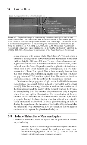
FIGURE 3-3 Bright-fi eld image of beam-tracing chamber showing the optical path
behind the L lens. The laser beam from the fi ber is visible in front of the aperture
2
because PDMS contains nanoparticles of silica that scatter light. The focused beam
in the beam-tracing chamber is visualized by the fl uorescence of a rhodamine dye
fi lling the chamber. (S. K. Y. Tang, C. A. Stan, and G. M. Whitesides, “Dynamically
reconfigurable liquid-core liquid-cladding lens in a microfluidic channel,” Lab Chip, 8,
(2008), 395–401. Reproduced by permission of the Royal Society of Chemistry.)
sealed channels with a razor blade (Fig. 3-2a; x-x’). This cut opens a
channel at the edge of the PDMS that has the dimensions of the fiber
(width × height ~ 100 μm × 100 μm). The open channel accommodat-
ing the optical fiber ends at a distance from the fluidic channel, and is
isolated from the fluids. Depending on the application, this distance
2
varies from a few 10s of microns (for L waveguides) to a few milli-
2
meters (for L lens). The optical fiber is then manually inserted into
this open channel. Index-matching liquids can be applied to fill any
air gap between PDMS and the optical fiber. The center of the fiber
channel is collinear with the center of the microfluidic channel.
To visualize the propagation of light inside the PDMS device, one
can introduce fluorescent dyes in a chamber fabricated in the optical
path [2]. This “beam-tracing” chamber is used for characterization of
2
the focal distance and the quality of the focused beam of the L lens,
for example (Fig. 3-3). The solution of dye fluoresces only in regions
where there was optical illumination. The concentration of the dye
solution should be sufficiently low such that the incident light could
propagate through the beam-tracing chamber without being signifi-
cantly attenuated or absorbed. To avoid photobleaching of the dye
during the experiment, the intensity of the incident light should also
be sufficiently low; alternatively, new dye solution can be injected
continuously to replace the photobleached dyes.
3-3 Index of Refraction of Common Liquids
Contrast of refractive index in liquids can be provided in several
ways, including
1. Different liquids: A wide range of common liquids are trans-
parent in the visible region of the spectrum, and have refrac-
tive indices ranging from 1.28 to 1.75 [3]. Table 3-1 lists the
refractive indices of some common solvents.